Did you know you can use the ScanNCuts DX225 and the SDX230 to create cut files for appliqué right from a .pes file? No software needed!
It takes just a little bit of work to get the right sequence(s) to use as cut data. You have to isolate such sequences from the rest of the elements of the design, but it’s really simple. It’s just a matter of picking the right sections of the design and deleting the ones that aren’t appliqué placement stitches.
Load Design
Save your embroidery design to a usb stick and place that stick into the ScanNCut. For this blog, I am using the Stegosaurus.pes file from the Lunch Box Quilts Quiltasaurus collection.
Load File with Appliqué into ScanNCut
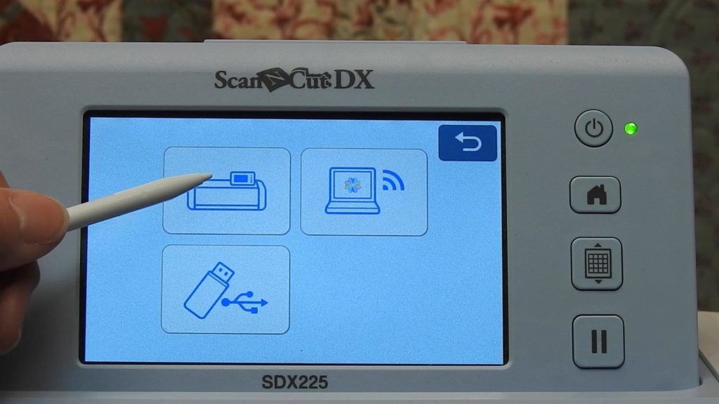
Retrieve the .pes file from the USB stick by selecting Retrieve Data and then the USB as the source. Other possible locations for files are the internal memory of the ScanNCut, the Canvas Workspace Cloud or on your PC through a direct connection via USB cable.
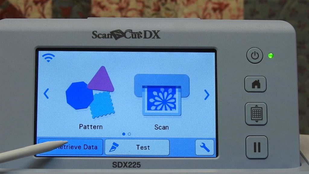
Retrieve Data 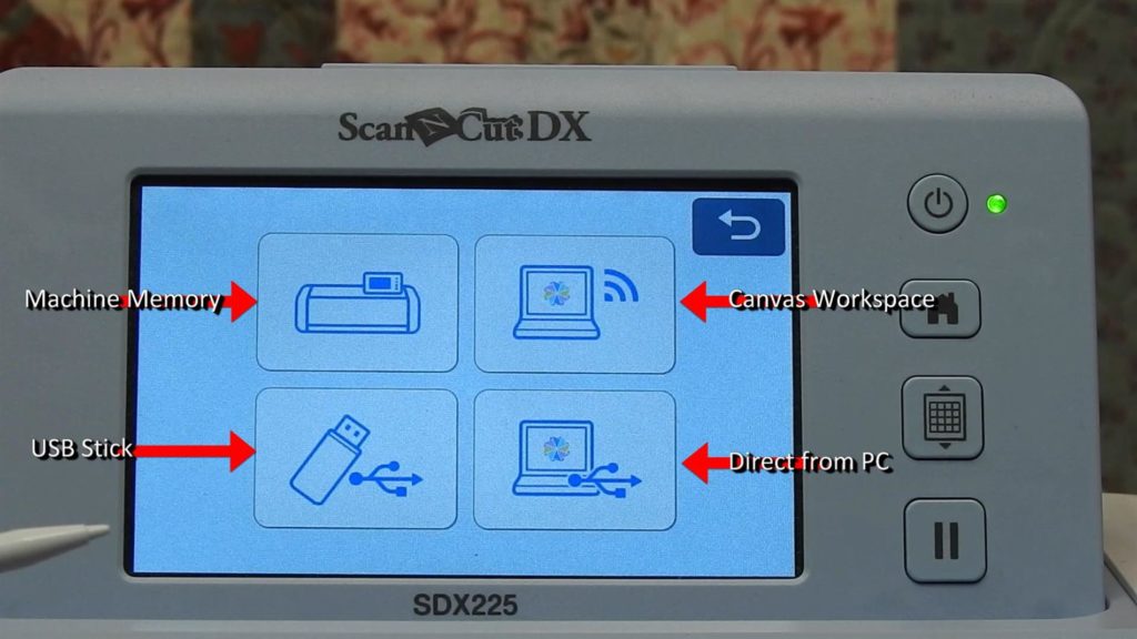
Choose Source of Data 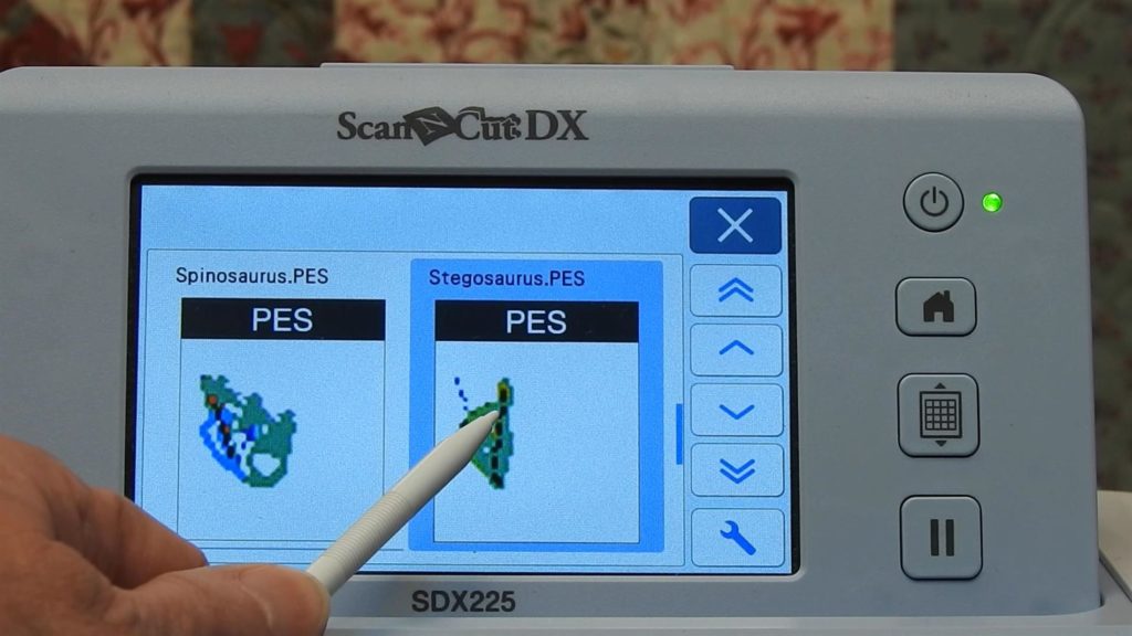
Select pes file
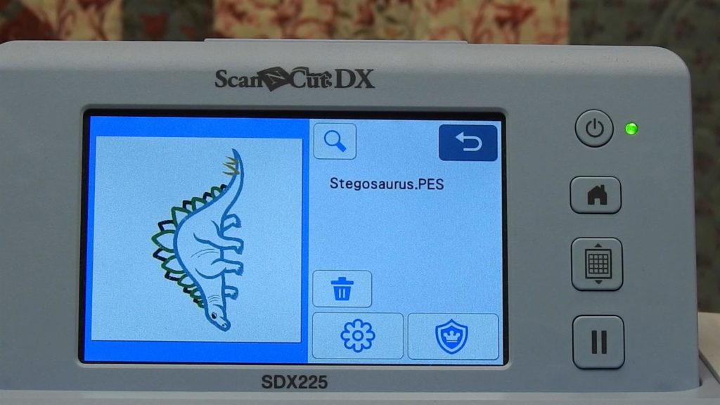
Tap the thumbnail and the design will load.
Look for Cut Data
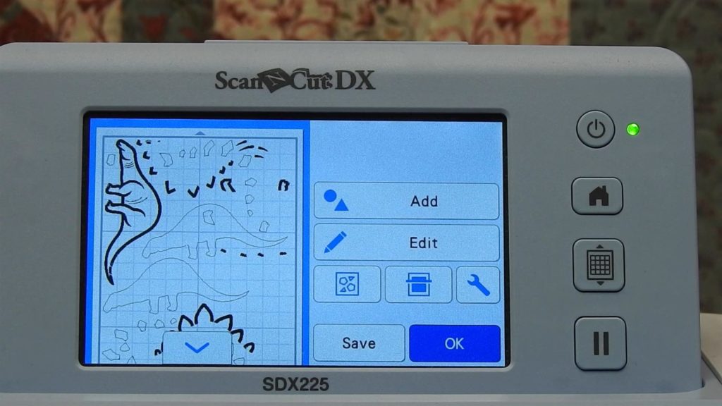
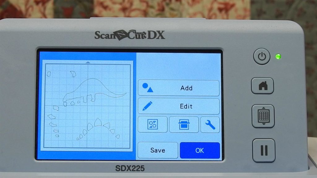
After the design has loaded, the screen will show two icons at the bottom, one that looks like a flower and one that looks like a shield.
The Shield Icon
The shield icon looks for appliqué cut information in the design. In the Brother world, when an appliqué is created in PEDesign or on a Brother embroidery machine, you can indicate that one or more parts of the design is “cut data” for an appliqué. That information is saved with the .embroidery file.
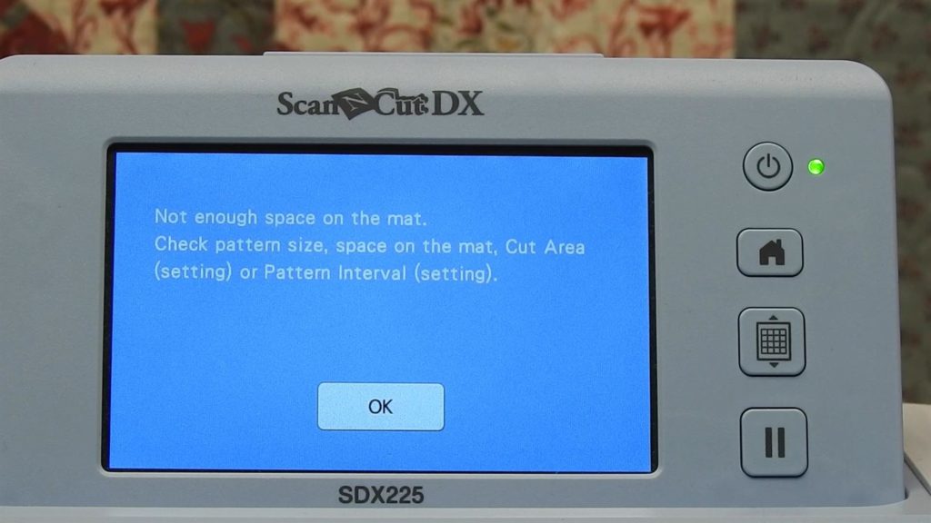
If you select that icon, you will likely get a message that there is no cutting line data found.
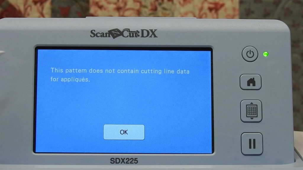
I have looked at pes designs with appliqués from a variety of providers have not found a single one that recognizes any part of an appliqué as cut data. So, it appears that it’s a “Brother thing”. The .pes or .phc file has to be created with that cut data on a Brother embroidery machine or Brother software. That’s a topic for another day.
The Flower Icon
So select the flower icon, not the shield icon.
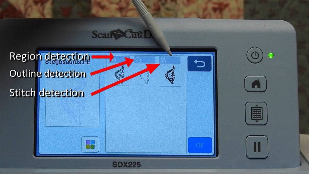
Tap the flower icon, and the design will show on the screen with three options to load information: by region detection, by outline detection or by stitch detection. Select stitch detection and all stitch sequences are loaded and will be grouped.
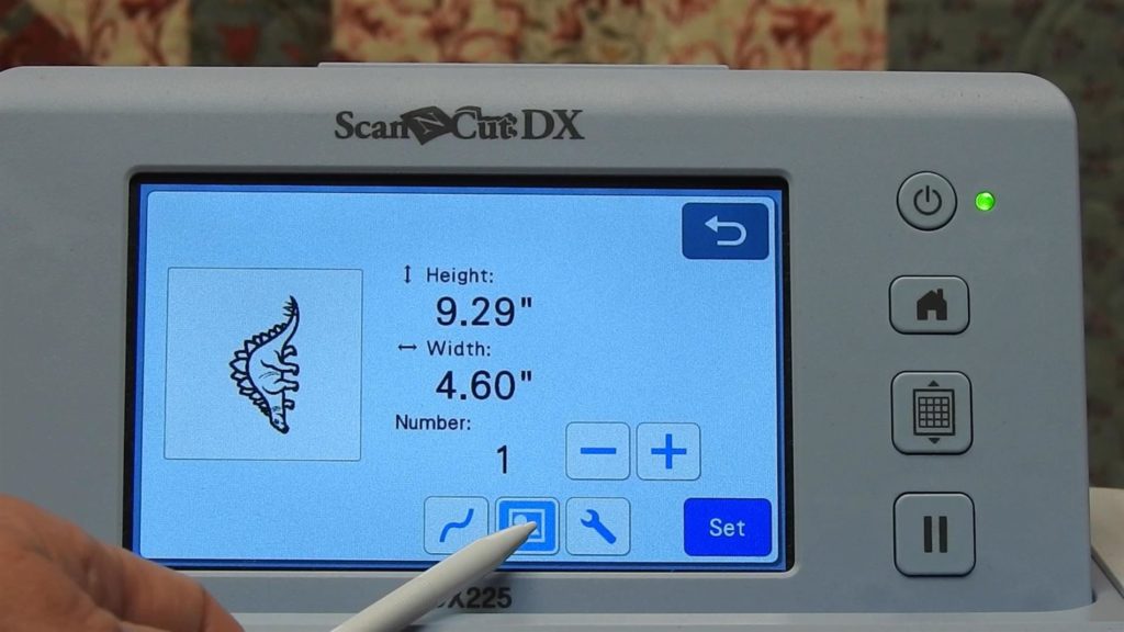
Ungroup All Elements
Click on the Group icon to ungroup all elements. This allows you to selectively delete those parts of the stitch out that you don’t need (and keep those you want).
Click on Set.
A Few Words About Appliqué
Now think about appliqués. A typical appliqué stitch sequence consists of three parts.
Placement Stitch
First is a placement stitch. This is usually a single run stitch that shows you where to place the fabric for the appliqué.
Tackdown Stitch
The next stitch sequence in an appliqué is the tack down stitch. This is often a double run stitch that tacks the fabric in place.
If your appliqué is not pre-cut, then after the tack down stitch you need to trim away excess fabric away from the appliqué, trimming close to the tack down stitching. If your appliqué is already cut out, no additional trimming is needed.
Cover Stitch
The final part of an appliqué is what I call the cover stitch. This stitch covers the raw edges of the appliqué with a satin stitch, a blanket stitch or a motif stitch. This stitch may follow immediately after the tack down stitch or it might be sewn later in the sequence.
In addition to the appliqué parts, there are usually additional embroidery elements that enhance and finish out the design.
So our task is to delete all those parts of the design EXCEPT the placement stitches for each of the appliqués.
Caution
One note of caution, here. We are using stitch data to create cut data , and the cut data will include all stitch information like tie offs. So the resultant cut data may not be a smooth cut line, but a series of short cuts, resembling stitches. By using the placement stitch to create cut data, it will be as simple and smooth as possible using this method.
Identify Applique Sequences to Save
Arrange Parts on Screen
In order to see the different elements of the design, select one of the arrange icons so the parts of the design are all separated out from each other.
Although the arrange feature is primarily for arranging the most efficient placement of items for cutting, now use it to separate all elements of the design to delete the unneeded ones.
The ScanNCut offers three ways to arrange items on the mat, so pick one. It doesn’t really matter which one they all result in the separation of the design elements on the mat.
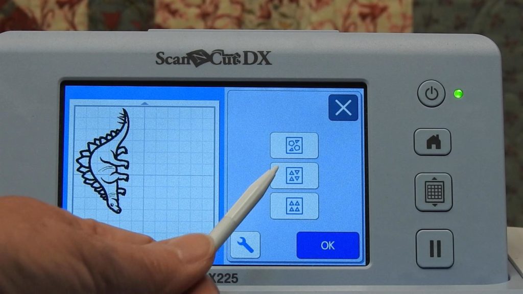
Select one of the arrangements and click OK. The ScanNCut will take a minute to process the design and separate all elements.
Mat Size
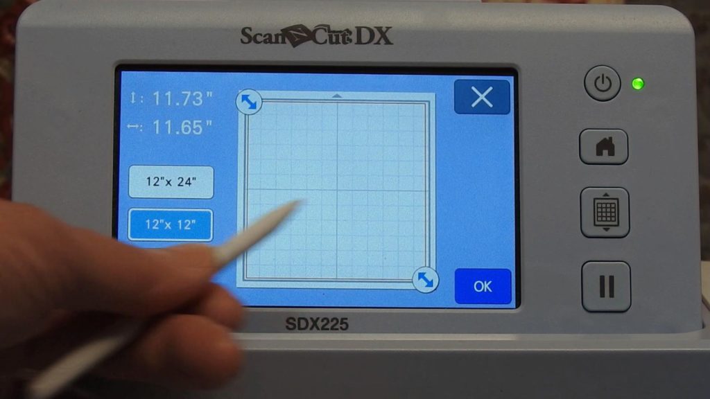
The Stegosaurus design has 16 different stitch sequences. So in order to see all of them on the mat, I had to select the 12″ x 24″ mat before I could successfully use the arrange icon. So, if there are more elements than can fit on a 12″ x 12″ mat, change your mat size to 12″ x 24″. It doesn’t matter if you don’t have this size mat; it’s just a temporary setting to be able see all parts of the design.
Change Mat Size
To change the mat size, click on the wrench and then from the settings select Cut Area , the forward arrow and select a cut area of 12″ x 24″. Click on OK.
Too many parts for a 12″ x12″ mat 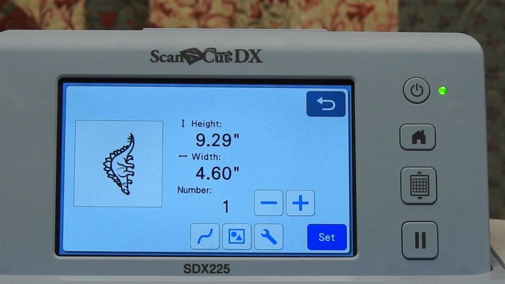
Select Wrench 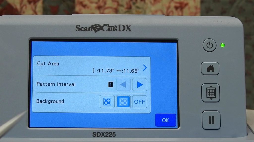
Click on Right arrow 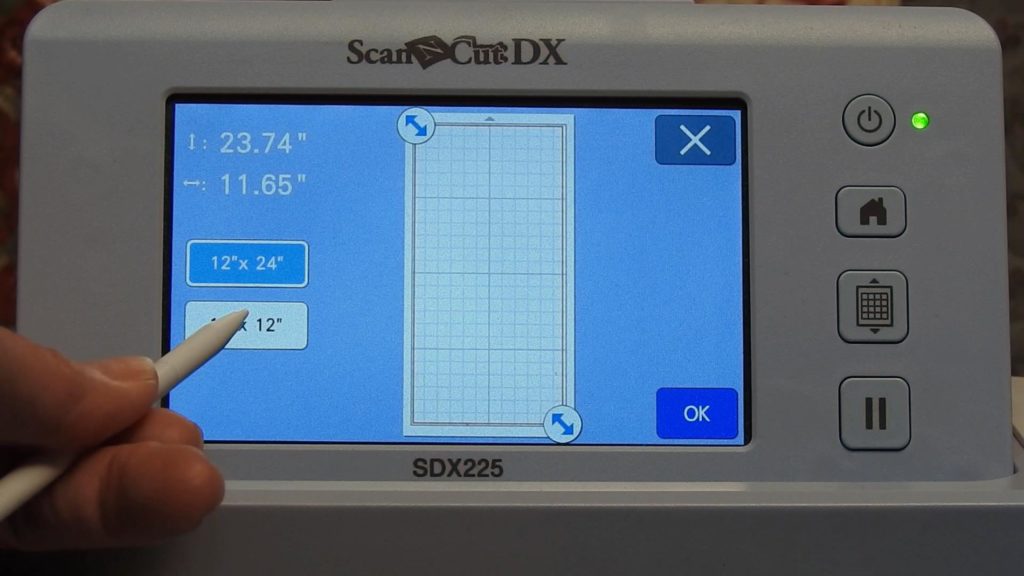
Select 12″ x 24″ mat
Re-arrange on Larger Mat
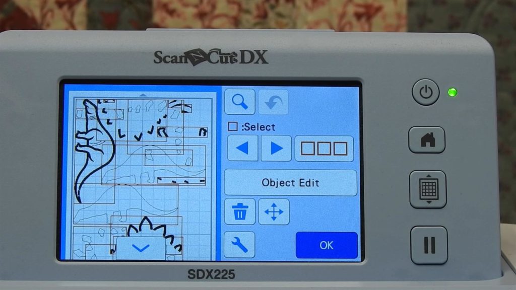
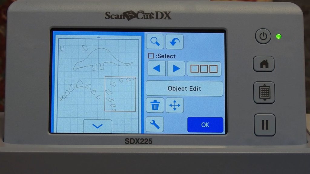
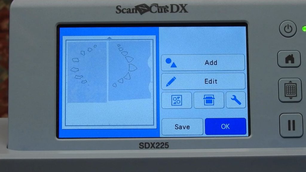
Again select one of the arrange icons. Now, the screen on the ScanNCut displays a rendering of a mat with all of the parts separated out.
Note: if using the 12 x 24 mat, scroll down using the down arrow to see the rest of the elements of the design.
Each sewing sequence in the design will be an element that you can save or delete. Select OK to select all elements as indicated by red boxes around each element.
Identify Placement Stitches for Appliqué and Delete All Others
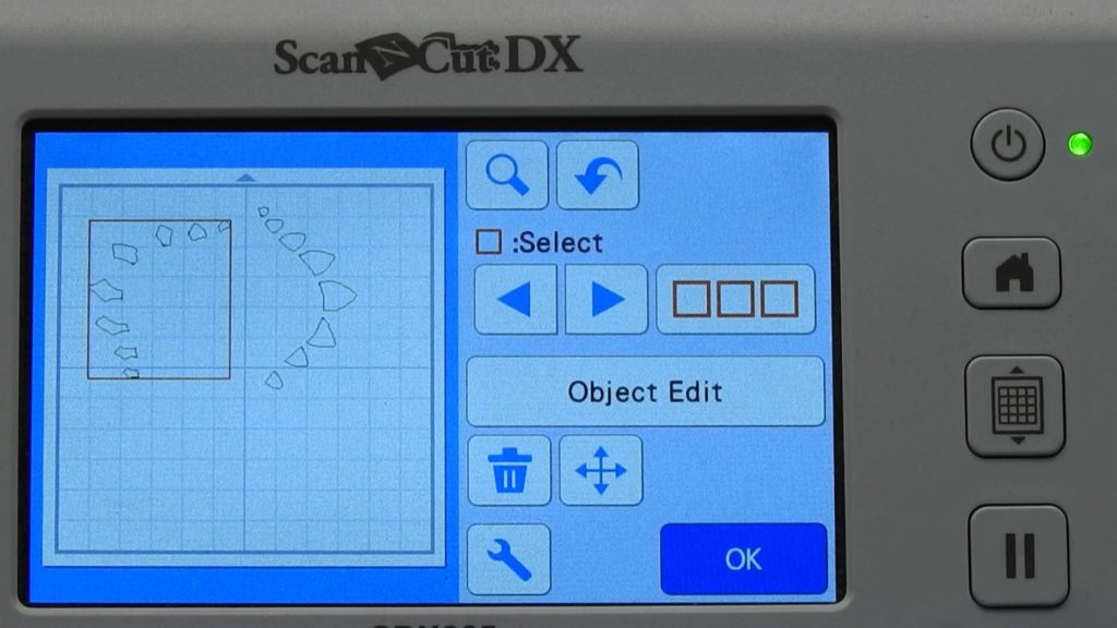
When you touch the Right Arrow under Select, the first element of the stitch out sequence will be selected.
Refer to the color chart that accompanied your designs to understand the sew-out sequence for your design.
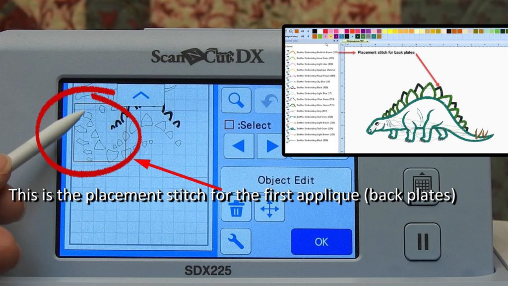
Placement Stitch #1
In the case of the Stegosaurus, the first sequence in the stitch out is the placement stitch for the back plates of the dinosaur. Keep that stitch sequence!
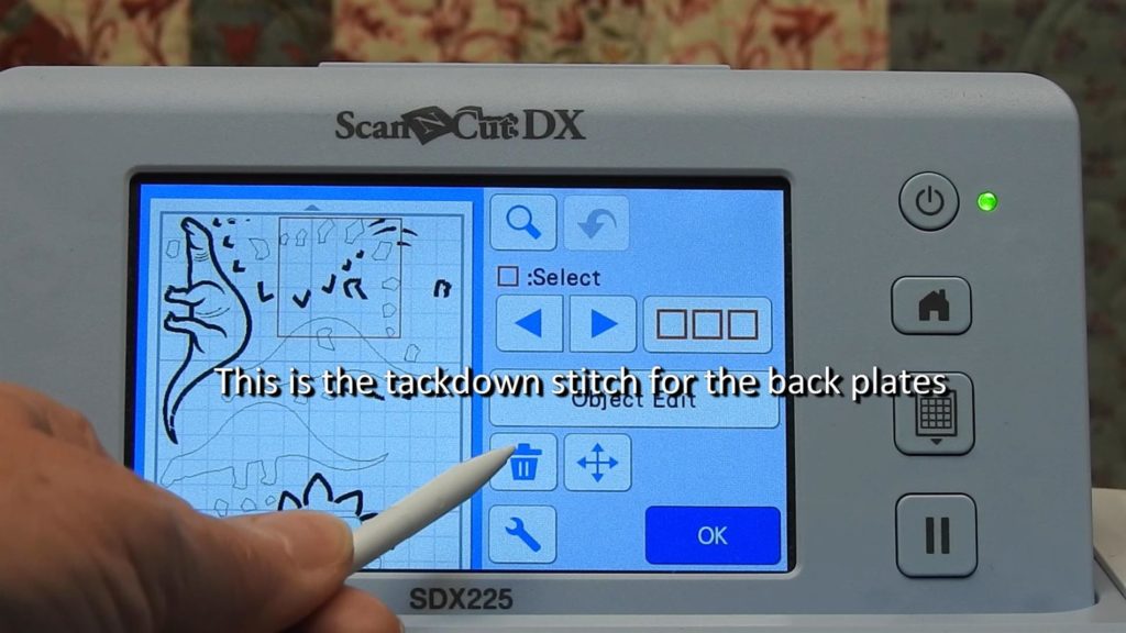
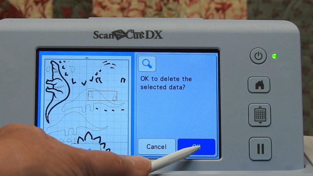
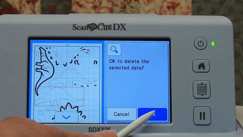
Touch the right arrow to select the next item in the stitch sequence. This is the tack down stitch for the appliqué. For the stegosaurus, it is the tack down stitch for the back plates. Delete this sequence as we do not want cut data from this sequence.
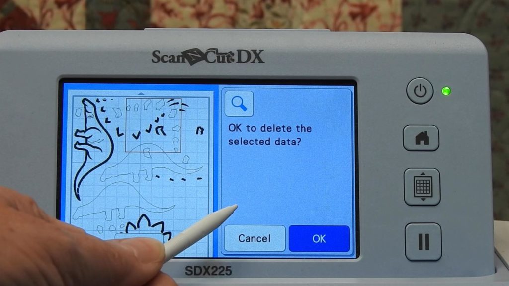
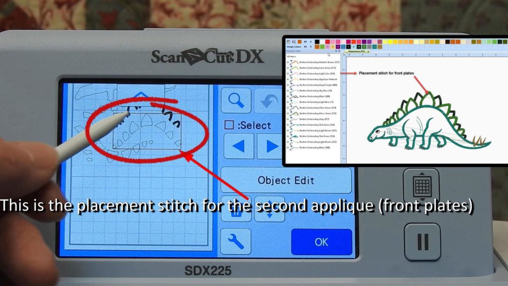
Placement Stitch #2
Once an item has been deleted, the next item in the sequence is automatically selected. So this is the third item in the stitch out, and for the Stegosaurus, it is the placement stitch for the front plates of the dinosaur. We want to keep that stitch sequence.
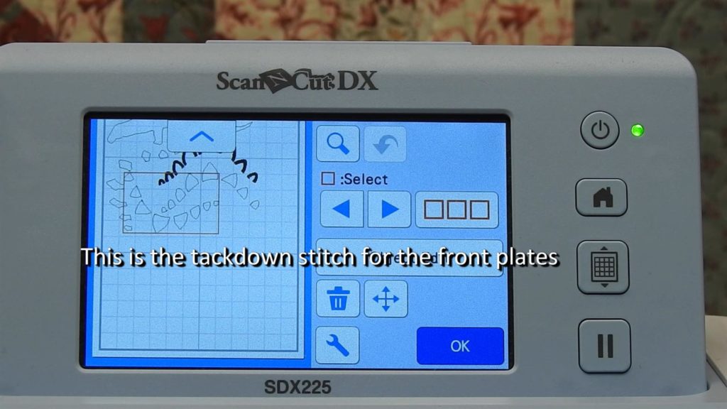
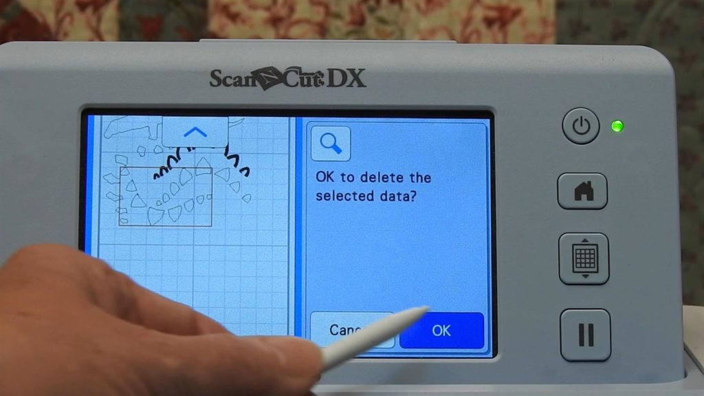
Placement Stitch #3
Touch the right arrow to select the next (4th) item in the sew out sequence (the tack down stitches for the front plates.) Delete that sequence.
The next item (5th) is automatically selected. This is the placement stitch for the dinosaur’s legs.
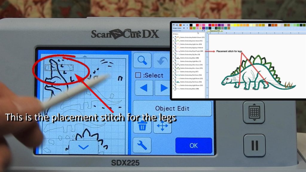
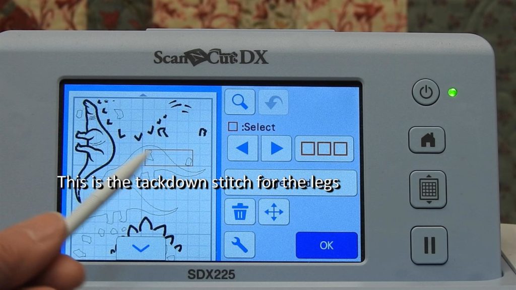
We need to keep these, so just select the right arrow to select the corresponding tack down stitch for the legs (6th). Delete this sequence.
Placement Stitch #4
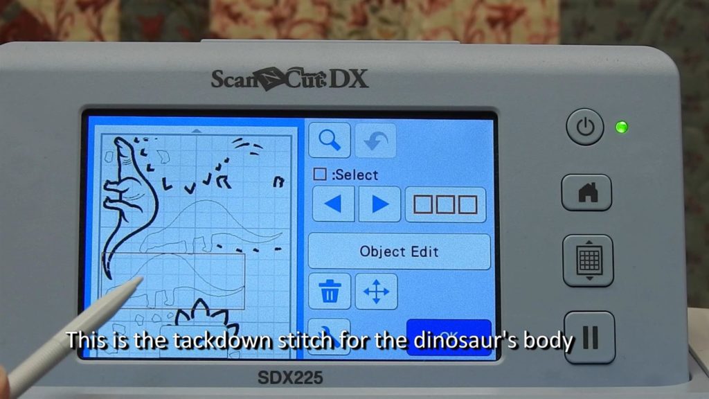
The next item (7th) is the placement stitch for the dinosaur’s body.
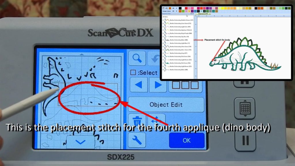
We need to keep this as well, so, as before, touch the right arrow to select the next sequence (8th), the tack down stitch for the dinosaur’s body. Delete this sequence.
Remaining Elements
Use your design color chart to determine how many appliqué are in the design and delete any stitch sequences not needed.
Delete all unneeded sequences so that the placement stitches for all appliqué in the design remain. Re-arrange them all to fit on a 12″ x 12″ mat, select the wrench icon, and change the mat size back to 12″ x 12″. Click OK.
Save the cut files to your machine, a usb stick or send it the Canvas Workspace cloud.
The placement stitches are now cut data for applique (an .fcm file), and can be cut out with the ScanNCut.
Offset
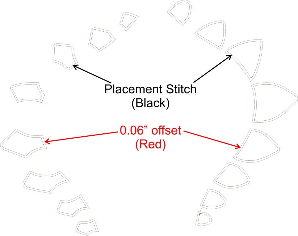
The placement stitch for a design is the exact size of the appliqué. Depending on the size and type of cover stitch, it is possible that the inside edge of the appliqué may not entirely be covered by a satin stitch, for example.
If this is problem, add an offset to the design so that it is cut slightly larger than the placement stitch.
If not in the edit function, select the element you want to add offset to, select Object Edit and then tap the offset icon. Enter the amount of offset to add.
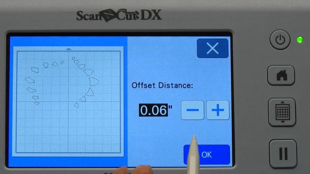
Don’t make it too much larger, or you’ll have to trim it so that the edge of the appliqué doesn’t show on the outside edge of the cover stitch. I add just a bit of offset (0.06”) to the appliqués before cutting them to make sure that the cover stitch will adequately cover all the raw edges.
Cut Appliqué
Place your fabric on your ScanNCut mat, and scan it to position the appliqué elements.
You’re ready to cut!
The Brother ScanNCut
For this blog, I used the ScanNCut SDX 225 with the auto blade. These machines take much of the guess work (and rework) out of cutting fabric for appliqué. View our companion video to this blog to see the ScanNCut SDX225 in action.
Visit your local Rocky Mountain Sewing and Vacuum store to see for yourself the wonderful features of the ScanNCut machines with the auto blade. We also have these machines for sale on our website. Please note, the SDX225 is currently on backorder, but we have a great deal on the newer SDX230D. Check it out!
Comments
Cathy Ellsaesser
If you are doing the method I described in the blog, keep in mind that you are actually using stitch data to created cut data. So the tiny swirls are stitches converted to lines. If you are using the placement stitch to create the cut data then try the tackdown stitch and vice versa. I have found that if the digitizer uses a double stitch for placement, then the conversion to cut data is not a smooth line. If you have a Brother embroidery machine OR editing software you can edit the color of the placement stitch to the color that Brother uses to signifiy that it is a cut line. Then save the edited .pes file and load that into the ScanNCut.
Hope this helps
Sandy
I had the same problem of an offset line not being created. The shapes were simple with no crossed lines. However, when magnified, the cut line was actually tiny swirls. This did not start happening until after I recently updated my machine.
Cathy Ellsaesser
Once you create the offset, select the original placement line and delete it.
Hope this helps.
Judy Van Otterloo
I have a SDX225, I was having issues with the pieces I scanned not covering the palacement line. So I tried to do the offset and it then cut both lines?? What did I do wrong.
Thanks
Cathy Ellsaesser
Lindsey,
I do know that an offset line cannot be created for a pattern with a complex shape. Without seeing what you are trying to create an offset from, I can’t really say for sure. But you can try to reduce the number of shapes or simplify the shapes and then try again. Also, make sure it is a closed shape.
Hope this helps and happy sewing .. or ScanNCutting!
Lindsey Herr
Good morning! I have a new SDX225F and was so excited to find this tutorial as it is exactly what I’m looking for!
However, when I go to apply the offset, it tells me “failed to create an offset line”
I really hope someone can help me with this!